Building a Wireless Remote
Now that you have build your bot with DPDT switches and a lot of wires, you were wondering what if had the bot had been a wireless one ?
The solution would be, to have a wireless remote control system to control the bot. Now cheapest solution to make a wireless remote control is- taking out the main circuitry from a wireless remote control toy and replace the motors with your desired actuators. But for techfests and good level projects (non just for hobby), I would prefer making this RF remote control.
Every remote control system consists of a Transmitter (Tx) and a Receiver (Rx). We will be using ASK (Amplitude Shift Keying) based Tx/Rx pair operating at 433 MHz. It can be interfaced with a microcontroller or can be used in remote control applications with the help of encoder/decoder ICs.
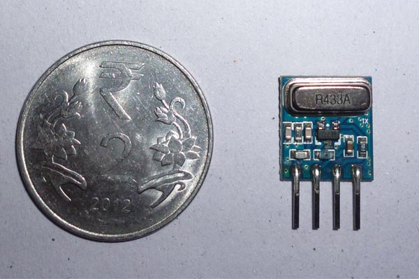
The Transmitter :
[ Front View ]
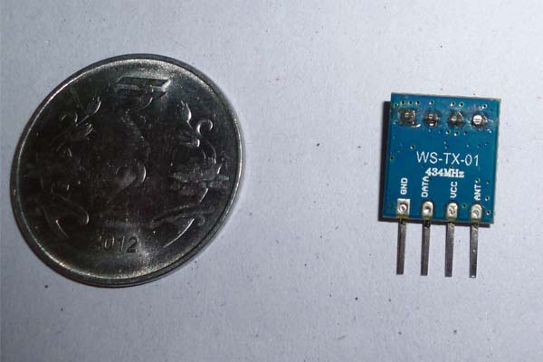
[ Rear View ]
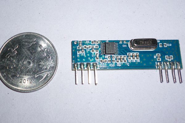
The Receiver :
[ Front View ]
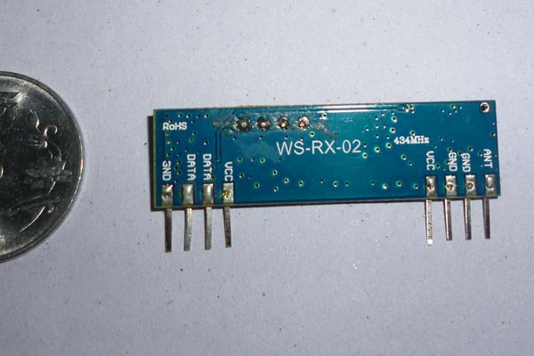
[ Rear View ]
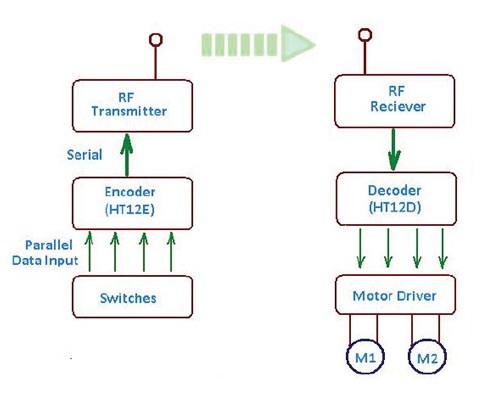
Block Diagram:
Main Circuit Diagram :
Attach wires of length 10cm to pins 4 and 8 of the Tx and Rx respectively. These will serve as the atennae. For short range (like when you are controlling your bot in the arena) you won't be needing the antennae. At the address pins (A0-A8) on HT12E(Tx side), if particular pins are shorted to ground, for eg: if pin A0 and A1 is connected to the ground; then untill unless the same is done on the address pins on HT12D(Rx side), connection won't be established. Hence you can also consider this process of setting address, as a method of shieldng your signals so that other remotes dont interfere with your transmission process.
Brief working :
At the Tx end, the encoder IC HT12E, takes in parallel data from the Tx, which is to be transmitted, packages the data into serial format and then transmits it with the help of the RF Tx module. At the Rx end, the decoder IC HT12D receives the signal via the RF Rx module, decodes the serial data and reproduces the original data in the parallel format.
In order to drive motors, we would need to connect a suitable motor driver at the output of
the decoder IC. At the receiver end the chip 7404 is basically a NOT gate. The HIGH state (by high state we mean a switch press condition) or 1 on the TX side is a LOW or 0 at the receiver side hence the 7404 is required to invert the signals again and feed it to the motor driver for motor control.

